Settings reference
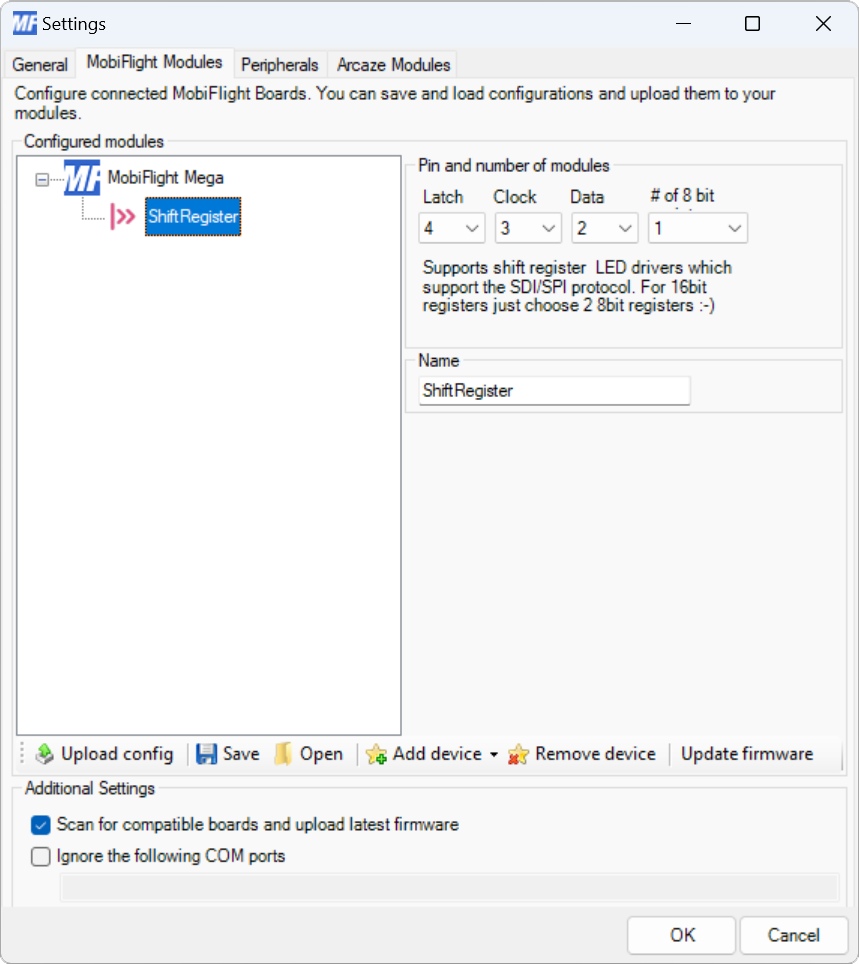
Modules dialog
| Setting | Description |
|---|---|
| Latch | The board pin connected to the latch pin of the shift register. All digital and analog pins are supported. |
| Clock | The board pin connected to the clock pin of the shift register. All digital and analog pins are supported. |
| Data | The board pin connected to the data pin of the shift register. All digital and analog pins are supported. |
| # of 8 bit registers | The number of 8-bit groups connected in series to the board. Chips with eight inputs count as one group. Chips with 16 inputs count as two groups. |
| Name | The name for the output shift register. Displayed in the output configuration dialog to identify the shift register when mapping a simulator variable to the output. |
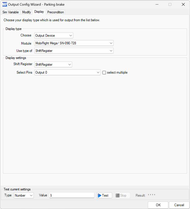
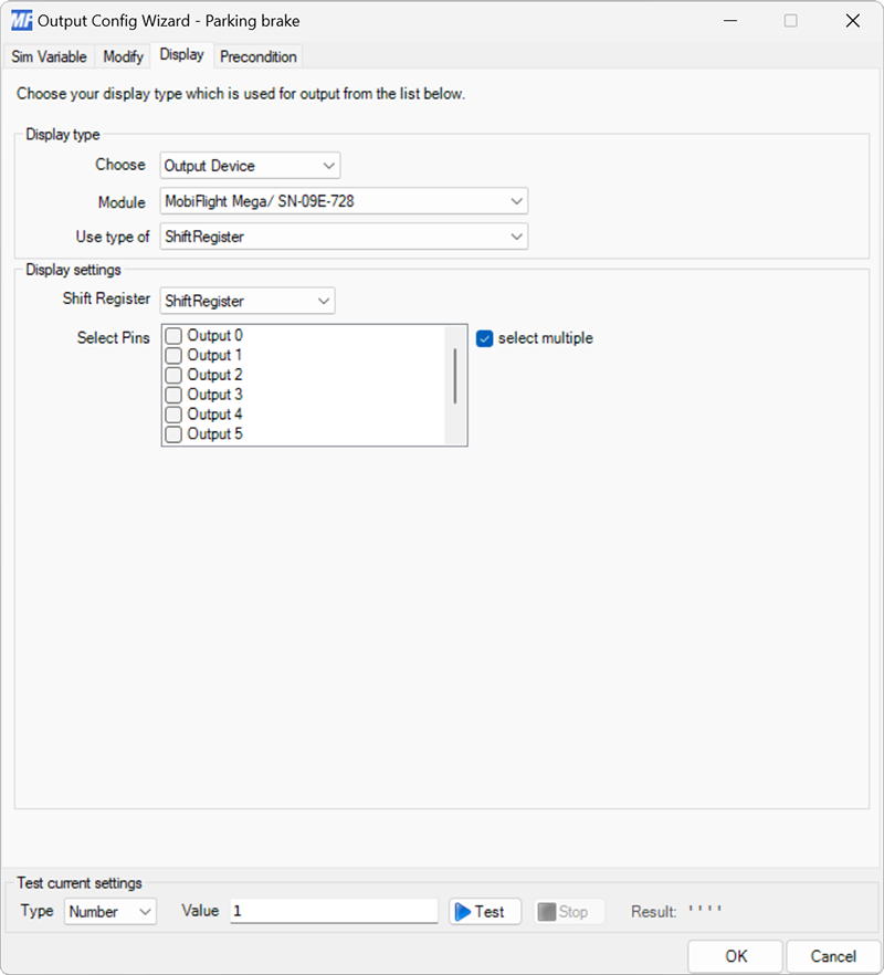
Output display configuration
| Setting | Description |
|---|---|
| Shift Register | The chain of shift registers to display the value on. |
| Select Pins | The output on the shift register chain to display the value on. |
| Select multiple | When checked, enables selecting multiple shift register outputs to display the value. |