Settings reference
Modules dialog
| Setting | Description |
|---|---|
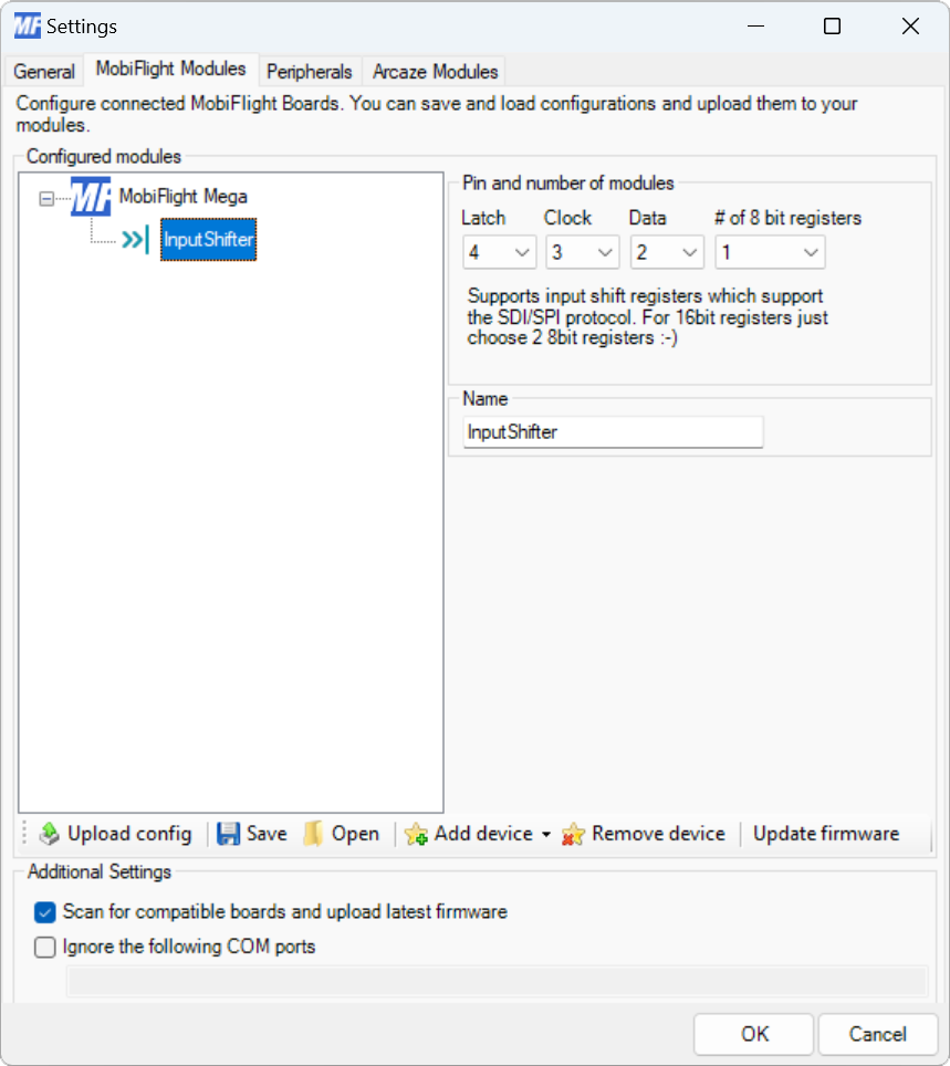
| Latch | The board pin connected to the latch pin of the shift register. All digital and analog pins are supported. |
| Clock | The board pin connected to the clock pin of the shift register. All digital and analog pins are supported. |
| Data | The board pin connected to the data pin of the shift register. All digital and analog pins are supported. |
| # of 8 bit registers | The number of 8-bit groups connected in series to the board. Chips with eight pins count as one group. Chips with 16 inputs count as two groups. |
| Name | The name for the input shift register. Displayed in the input configuration dialog to identify the shift register when mapping the input to a simulator event. |
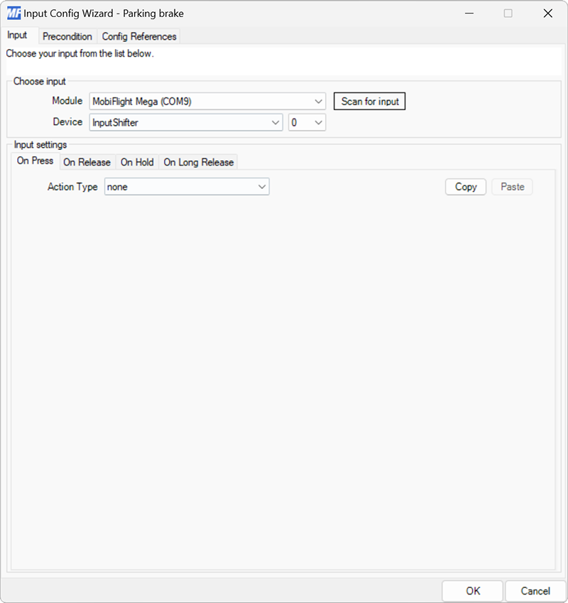
Input configuration
Input shift registers have the same input setting events as buttons and switches.
Use the Device dropdowns to select the input shift register and specific input on the chain of shift registers to use.